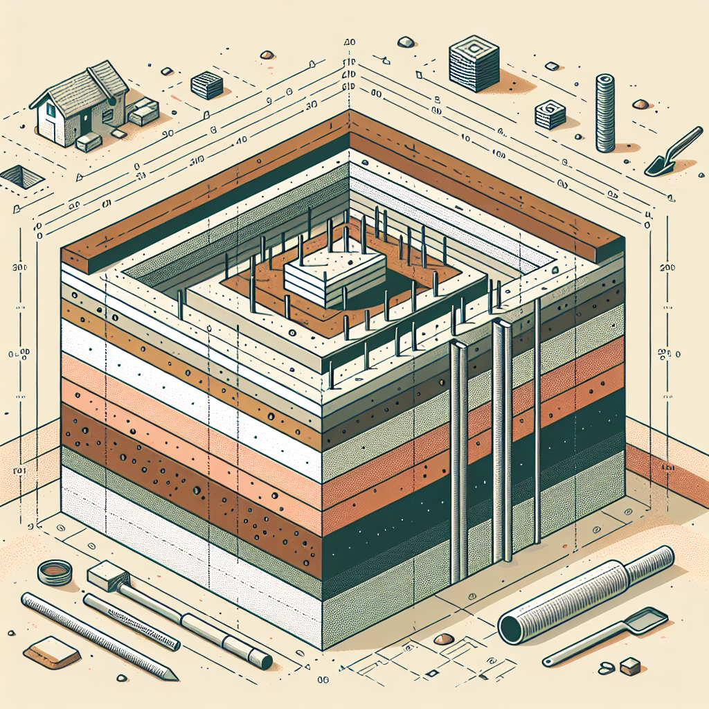
Pile foundations move loads from structures to deeper, stronger soil layers when surface soils cannot carry the weight. Performing clear calculations helps pick pile size, type, and number so the structure stays safe and stable.
This article explains the core ideas behind pile foundation design and walks through practical calculation steps. It keeps formulas and checks focused and easy to apply on typical projects.
Basic principles of load transfer
Piles transfer vertical and lateral loads by bearing on firm strata and by friction along their shaft. Understanding which mechanism dominates is key to sizing piles and predicting settlement.
Soil conditions, pile material, and installation method change how loads move into the ground. Early planning and good subsurface data reduce uncertainty in design.
Types of loads
Vertical loads include dead load, live load, and occasional design loads such as wind or seismic vertical components. Lateral loads come from wind, seismic forces, or retained earth pressure.
Pile design separates these into axial and lateral checks, with additional attention to uplift, dynamic actions, and eccentricity where applicable.
Soil reaction mechanisms
Two main reactions support piles: end-bearing (pile tip rests on firm layer) and shaft friction (skin resistance along the pile). Many piles use a combination of both.
Soft surface soils rely more on shaft friction while dense sand or rock layers provide strong end-bearing capacity. Laboratory and in-situ tests tell which applies.
Step-by-step calculation process
Start calculations after a proper site investigation report with borings, SPT or CPT results, and lab data. Clear inputs keep results reliable and defensible.
The process below shows common checks: axial capacity, group effects, settlement, and lateral behavior. Each step includes practical formulas and decision points.
Estimate axial capacity
Axial ultimate capacity has two parts: ultimate end-bearing (Qp) and ultimate skin friction (Qs). Sum them to get the pile’s ultimate axial capacity (Qu).
- End-bearing: Qp = Ap x qp, where Ap is pile tip area and qp is allowable bearing of the supporting layer.
- Skin friction: Qs = Σ (Asi x fi) over pile length, where Asi is surface area in layer i and fi is unit skin friction from tests or correlations.
Use local code factors and load factors to convert ultimate values to design or allowable capacities.
Group capacity and effects
Pile groups interact through overlapping stress bulbs in the soil, which reduces group capacity below the sum of single piles. Account for group efficiency when sizing pile layouts.
Common methods include group reduction factors, numerical analysis, or simplified models that consider spacing, depth, and pile type.
Settlement estimation
Settlement for piles has two parts: settlement of the supporting stratum that bears the pile tips and settlement due to skin friction and shaft deformation. Use layer stiffness and pressure distribution to estimate net settlement.
For piles ending in soft compressible layers, check long-term consolidation. For piles in dense sand or rock, settlement is usually small but must still be quantified.
Lateral capacity checks
Lateral load behavior depends on soil stiffness, pile length and flexural stiffness, and load height. Methods include p-y curves, empirical charts, and beam-on-elastic-foundation models.
Perform lateral checks when horizontal loads or overturning moments are significant, and account for group effects on lateral stiffness.
Choosing pile type and size
Selecting pile type affects capacity, cost, and constructability. Match the pile system to ground conditions, access, noise limits, and installation risks.
Typical pile options include driven piles, bored (cast-in-place) piles, and ground improvement alternatives. Each has trade-offs in performance and site impact.
Driven piles
Driven piles are prefabricated elements (concrete, steel, timber) hammered into the ground. They often provide high shaft friction and reliable end-bearing if they reach dense strata.
Advantages include predictable capacity from dynamic testing (PDA) and quick installation, but they can be noisy and cause vibrations.
Bored and cast-in-place piles
Bored piles are made by excavating a hole and pouring concrete with reinforcement. They work well where vibrations must be minimized or where large diameters are needed.
Quality of the bore and continuity of concrete placement control capacity. Temporary casing or drilling fluids may be needed in unstable soils.
Choosing diameter and length
Start with an economical diameter that meets constructability and reinforcement needs. Then compute required length to mobilize needed end-bearing or skin friction.
Check practical limits like crane reach, site access, and neighboring structures before finalizing pile dimensions.
Design checks and settlement assessment
After initial sizing, run the core design checks: bearing capacity, structural strength, serviceability, and durability. Each has specific inputs and acceptable limits set by codes.
Keep documentation of assumptions and safety factors so reviews and approvals go smoothly.
Bearing capacity check
Compare design axial load (including eccentricity and group effects) to the pile group’s allowable capacity. Apply partial safety factors as required by local standards.
For uplift, ensure skin friction or anchor resistance exceeds maximum tensile loads with the correct factors.
Settlement evaluation
Serviceability limits often control design. Calculate immediate settlement using elastic methods and long-term settlement from consolidation where applicable.
Where group settlement is critical, use refined analysis or finite element models to capture interaction and nonlinearity.
Structural checks of the pile
Design the pile section for combined axial load and bending moment using reinforced concrete or steel design rules. Check shear, bending, and slenderness effects.
Consider construction stages: temporary loads during driving or concreting can govern reinforcement and section design.
Common pitfalls and practical notes
Real projects often fail to account for uncertainties in soil data, installation damage, or seasonal effects. Anticipating these avoids costly redesigns or repairs.
Keep decisions conservative where data is sparse, and update designs once more site information is available.
Inadequate site investigation
Too few borings or missing in-situ tests lead to wrong assumptions on layer stiffness and strength. Increasing the number of deeper tests often saves costs later.
Use CPT or well-calibrated SPT correlations to estimate skin friction and end-bearing more reliably.
Ignoring group interaction
Assuming piles act independently can oversize foundations or cause unexpected settlement. Evaluate group effects, especially for closely spaced piles.
Adjust group layouts or increase pile length if interaction reduces overall capacity too much.
Overlooking installation impacts
Driving can densify or loosen surrounding soils depending on method and ground type. Drilling can alter effective stress and require careful casing or fluid control.
Plan installation monitoring like pile driving records or integrity tests to verify design assumptions.
Conclusion
Sound pile foundation design relies on good subsurface data, clear calculation steps, and checks for capacity, settlement, and structural adequacy. Practical choices on pile type and spacing reduce risk and cost.
Keep records of assumptions, use conservative values when data is limited, and update the design if new information becomes available during construction.
Frequently Asked Questions
What tests give the best input for pile capacity?
Cone penetration testing (CPT) and standard penetration testing (SPT) are commonly used. CPT provides continuous profiles of resistance and is very useful for friction estimates. Dynamic testing (PDA) after driving confirms capacity and can detect anomalies.
How is pile length chosen in a layered soil profile?
Choose length to reach a competent bearing layer or to mobilize enough skin friction. Combine calculations of Qp and Qs and factor in group effects. Practical constraints like reach and installed pile tolerance also matter.
When should lateral capacity be checked?
Check lateral capacity when horizontal loads, moments, or overturning actions are significant. This includes tall structures, retaining walls, and locations with wind or seismic demands.
Can short piles work in soft soils?
Short piles rely heavily on skin friction and may not be suitable if the near-surface layers are very soft. In such cases, longer piles to reach dense layers or alternative ground improvement may be needed.
How do seasonal groundwater changes affect pile performance?
Water table fluctuation changes effective stress and can alter consolidation behavior and skin friction. Design should consider worst-case groundwater conditions and potential corrosion or durability effects.
Should pile driving records be part of the project file?
Yes. Hammer logs, blows per inch, and dynamic test results help verify capacity and detect anomalies. They form an important part of quality assurance and as-built documentation.