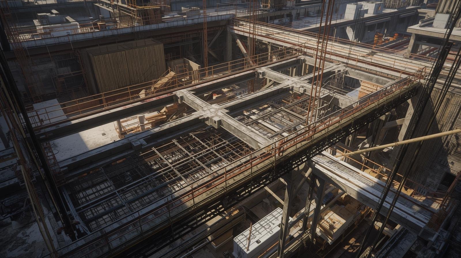
Beam lap splice location must be selected from the bending-moment diagram, reinforcement stress and approved structural detailing—not from a universal “top bars here, bottom bars there” rule. A simply supported beam, continuous beam and seismic-resistant frame can have different tension regions and splice restrictions. This article focuses on how to interpret those moment zones; for IS 456 lap-length provisions, see our main beam lapping zone guide and the separate IS code detailing article.
What Is a Beam Lapping Zone?
The beam lapping zone refers to a specific area in a reinforced concrete beam where two reinforcement bars overlap to transfer load and maintain structural strength. The overlap length, known as the lap length, ensures that stress is effectively transferred from one bar to another without creating weak points in the structure.
Lapping is usually done when the bar length required in design drawings is more than the available standard length of reinforcement bars (typically 12 meters). To continue the reinforcement without welding or mechanical couplers, overlapping the bars becomes a practical and economical solution.
Purpose of Beam Lapping Zone
The main purpose of the beam lapping zone is to maintain structural continuity and load transfer across the joint between two bars. When properly designed and placed, the lapping zone ensures that the beam can resist bending, shear, and tensile stresses effectively. The zone helps:
- Transfer stress between reinforcement bars
- Avoid weak joints or discontinuities
- Maintain ductility and flexibility in beams
- Enhance the beam’s ability to resist tension forces
In short, a well-designed lapping zone contributes significantly to the durability, safety, and efficiency of the entire structure.
Location of Beam Lapping Zone
Locate a potential splice only after identifying which reinforcement is in tension and how the bending moment varies along the member. A lower-moment region may be preferable, but IS 456 restrictions, splice proportions, bar arrangement, shear reinforcement and any seismic detailing rules must also be satisfied. The final position belongs on the approved structural drawings.
Simply Supported Beam under Gravity Loading
For a typical simply supported beam under downward gravity loading, positive bending moment develops within the span: bottom reinforcement is generally in tension near mid-span, while top reinforcement is generally in compression in the central span. The bending moment reduces toward the supports. This explains why lap splices are commonly kept out of the high positive-moment region when the design allows.
This is not a fixed instruction to put every bottom-bar lap at the support. Shear, anchorage, end-zone stresses, bar curtailment, support detailing and the code’s splice-location limits still need to be checked.
Continuous Beam
A continuous beam can have negative bending moment over supports and positive bending moment in spans. Top reinforcement is generally in tension over supports, while bottom reinforcement is generally in tension in positive-moment regions. Therefore, the top and bottom splice locations must be assessed separately from the actual moment envelope and reinforcement stress under the relevant load combinations.
Seismic-Resistant Beam
In a ductile moment-resisting frame, earthquake effects can reverse the bending moment and cause yielding near beam-column joints. A splice that appears to be in a low-stress region under gravity loading may be unsuitable under seismic actions. Apply the governing IS 13920 provisions and the approved ductile-detailing drawings; never rely on a simple support-versus-midspan rule.
Lap Length in Beam Lapping Zone
Under IS 456:2000, Clause 26.2.5.1, lap length depends on the type of stress and the calculated development length (Ld). In flexural tension, the lap length including the anchorage value of hooks is the greater of Ld and 30φ. In direct tension, it is the greater of 2Ld and 30φ. In compression, it is the development length in compression, but not less than 24φ. These provisions must be read with the other splice detailing requirements and applicable amendments.
A fixed 40φ or 50φ value is not a universal substitute for calculating Ld. Do not use a bar-diameter lookup table as an approved lap length unless the structural designer has verified the concrete grade, steel grade, stress condition, bar position, percentage of bars spliced and confinement details.
Factors Affecting the Beam Lapping Zone
Several factors influence where and how lapping should be done in a beam. These include:
1. Bar Diameter
Larger diameter bars require longer lap lengths to ensure adequate stress transfer.
2. Type of Stress (Tension or Compression)
Lap length varies depending on whether the bar is in tension or compression.
3. Concrete Grade
Higher-grade concrete provides better bond strength, potentially reducing lap length requirements slightly.
4. Bar Type
Deformed bars offer better bonding than plain bars, which means shorter lap lengths can be used.
5. Position in Structure
Beams in critical areas such as seismic zones may require extended lap lengths or alternative joining methods like couplers or welding.
Common Mistakes in Beam Lapping Zone
Errors in beam lapping zones can lead to serious structural problems such as cracks, deflection, or even failure. Common mistakes include:
- Lapping in high-stress zones
- Inadequate lap length
- Incorrect staggering of lap joints
- Lapping more than 50% of bars in the same section
- Using damaged or rusted bars for lapping
To prevent such issues, always follow the guidelines provided in the design drawings and building codes.
Best Practices for Beam Lapping Zone Construction
1. Stagger the Laps
Laps should not be placed at the same cross-section; they should be staggered to distribute stresses evenly.
2. Avoid Lapping in Maximum Stress Zones
Never place laps where the beam experiences maximum bending moments.
3. Provide Adequate Cover
Ensure that the concrete cover is maintained even in lapping zones to prevent corrosion.
4. Tie the Bars Properly
Proper binding of bars with steel wire ensures they remain in position during concreting.
5. Maintain Clean Surfaces
Bars should be free from rust, oil, and dust for effective bonding with concrete.
Difference Between Lap Length and Development Length
| Parameter | Lap Length | Development Length |
|---|---|---|
| Definition | The length required to overlap two bars for stress transfer | The length required to anchor the bar in concrete to prevent pullout |
| Purpose | To connect two reinforcement bars | To develop full stress in the bar |
| Formula / design basis | Calculated from the applicable lap-splice provisions for the stress condition and development length; not a universal 40d rule | Calculated from bar stress, diameter and design bond stress under the applicable code |
| Application | Used when bar length is insufficient | Used at beam-column joints, anchorage zones |
Understanding this difference helps in accurate detailing and construction.
How Beam Type Changes Lap Splice Decisions
The following descriptions explain the usual bending behaviour under common gravity loading. They are not splice-location instructions; actual locations must be selected from the design moment envelope, reinforcement stress, code limits and approved drawings.
1. Simply Supported Beams
Under typical downward gravity loading, positive bending moment causes bottom reinforcement to be in tension around mid-span. The moment reduces toward the supports. Where the design permits, lap splices in the tension reinforcement are therefore kept out of the high positive-moment region. Do not automatically splice bottom bars at the support: anchorage, shear, end-zone detailing and required development length must also be checked.
2. Continuous Beams
Continuous beams develop negative moments over supports and positive moments within spans. Top reinforcement is generally in tension in negative-moment regions, while bottom reinforcement is generally in tension in positive-moment regions. Splice positions for each bar layer must be assessed from the actual moment envelope and applicable code limits, not from a fixed “top near support / bottom near mid-span” rule.
3. Cantilever Beams
For a typical cantilever under downward gravity loading, the top reinforcement is in tension near the fixed support and the bending moment reduces toward the free end. The top tension bars must be developed and anchored into the support as designed. Do not place a lap in the critical fixed-end region unless the design and applicable detailing rules explicitly permit it.
Advantages of Proper Beam Lapping Zone
Proper lapping ensures the beam performs as designed. Some key benefits include:
- Improved load distribution
- Increased structural strength
- Reduced risk of bar slippage
- Enhanced durability of the structure
Alternatives to Beam Lapping
In certain cases, alternatives are preferred over lapping:
1. Mechanical Couplers
Used in high-strength or seismic zones to eliminate laps and reduce congestion.
2. Welding
Bars can be joined by butt or lap welding, though it requires skilled labor and quality control.
3. Extended Bars
Using longer bars can reduce the need for lapping altogether.
FAQs About Beam Lapping Zone
1. What is the maximum percentage of bars that can be lapped at one section?
As far as possible, not more than half the bars should be spliced at one section. Where more than half the bars are spliced at a section, or where splices occur at sections of maximum stress, IS 456 requires special precautions such as increased lap length and other detailing measures. Follow the exact clause and approved structural drawings.
2. Can lapping be done in the tension zone of a beam?
IS 456 provides lap-splice requirements for flexural tension, so a tension splice is not automatically prohibited. However, its position must satisfy the code’s moment and splice-location limits, the required lap length and the design’s detailing conditions. For seismic-resistant beams, additional IS 13920 restrictions apply.
3. What is the code reference for lapping?
Lapping guidelines are provided in IS 456:2000 (Clause 26.2.5.1).
4. Is welding better than lapping?
Welding offers better strength but requires skilled labor, quality control, and may increase cost.
5. How to ensure quality in beam lapping zones?
By following IS code provisions, maintaining lap length, proper bar alignment, and staggering laps.
Conclusion
The beam lapping zone is a critical part of reinforced concrete construction. When properly designed and executed, it ensures structural continuity, strength, and durability. Engineers must understand where and how to lap reinforcement bars based on stress zones, lap length requirements, and design codes. Proper attention to this detail can prevent future structural issues and enhance the overall performance of a building.